Fun Tips About What Are The Conditions For A Series Circuit

Understanding Series Circuits
1. What Exactly Is a Series Circuit?
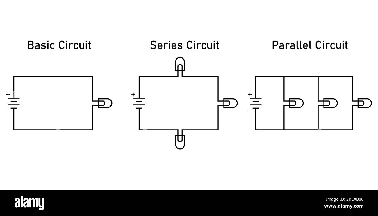
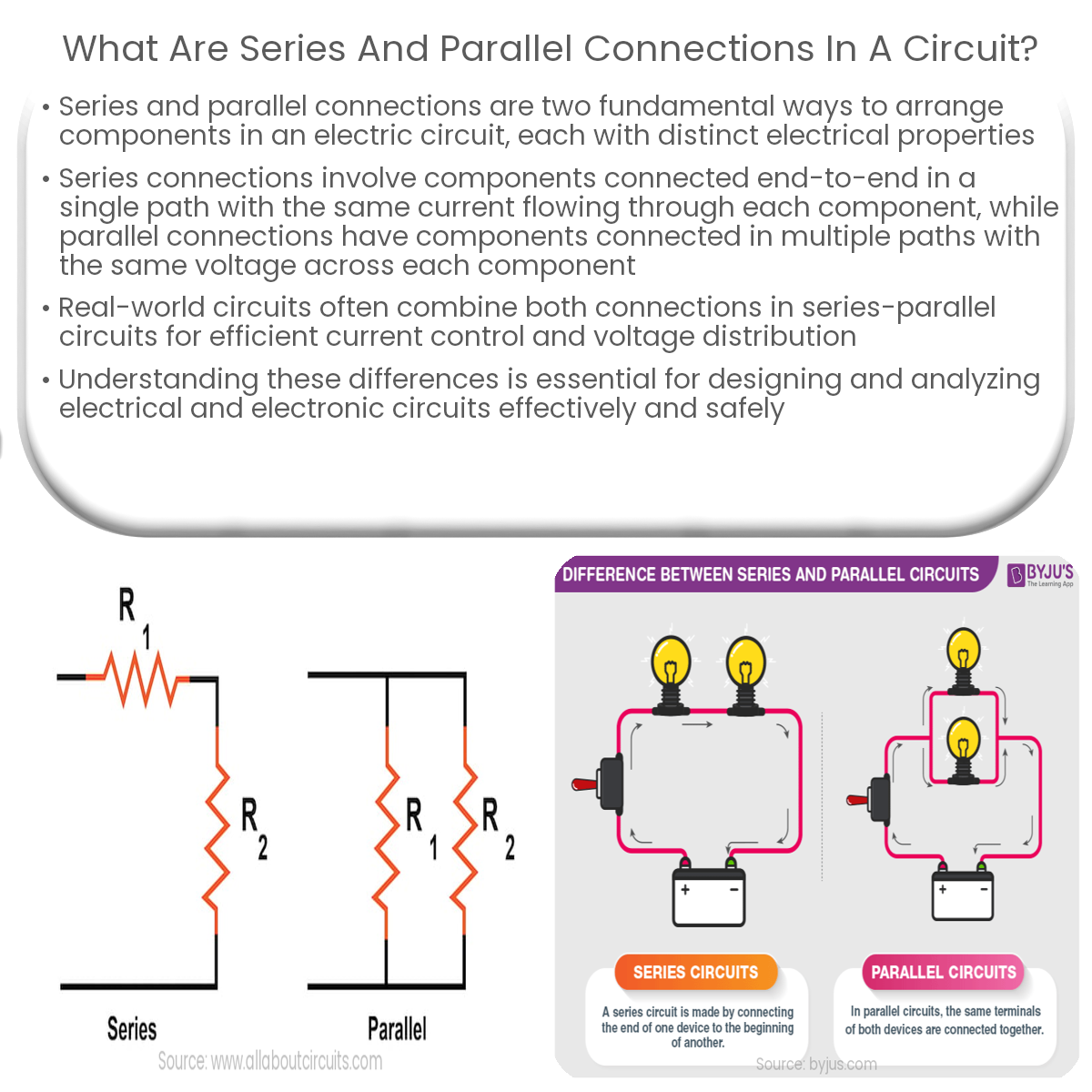
Ever wondered how those Christmas lights manage to blink in such a captivating way? Or perhaps you're curious about the inner workings of your old walkman? Well, chances are, series circuits are involved! At their core, a series circuit is a straightforward arrangement where components are connected one after the other, forming a single, unbroken path for the electric current to flow. Imagine a single lane highway — that's a series circuit in a nutshell. If one car breaks down (or one component fails), the entire road (or circuit) grinds to a halt.
Think of it like this: you've got a battery (the power source), and then, say, three light bulbs. Instead of each bulb having its own direct connection to the battery, they're all linked in a chain, one after the other. The current leaves the battery, passes through the first bulb, then the second, then the third, and finally returns to the battery. Simple, right?
It's that "single path" thing that's really key. There are no forks in the road, no alternate routes for the electrons to take. This has some pretty significant consequences for how the circuit behaves, which we'll get into shortly. But first, let's ditch the jargon and get practical. We are here to understand this, not be intimidated by it!
So, picture that chain of Christmas lights again. If one of those little bulbs burns out, the whole string goes dark. That's because the circuit is broken, and the electricity can no longer complete its journey. A bit frustrating when it happens, but it perfectly illustrates the fundamental principle of a series circuit!

Key Conditions for a Series Circuit to Function
2. What Makes a Series Circuit, Well, a Series Circuit?
Okay, so we know what a series circuit is. But what specific conditions need to be met for it to actually be a series circuit and work like one? Let's break it down. There are a few non-negotiable rules that define the behavior and functionality of this type of circuit.
First and foremost, it must have a single path for current flow. This is the golden rule, the defining characteristic. No branching, no parallel routes, just one continuous loop. If you see any points where the current can split, you're not looking at a series circuit anymore. Remember that highway? Only one lane!
Second, the current is the same throughout the entire circuit. Because there's only one path, all the electrons have to squeeze through each component in turn. There's no diverting around anything. So, the amount of current flowing into the first component is exactly the same as the amount flowing out of the last component (and everywhere in between). It's like a fixed amount of water flowing through a pipe; the same amount of water passes each point in the pipe at any given time.
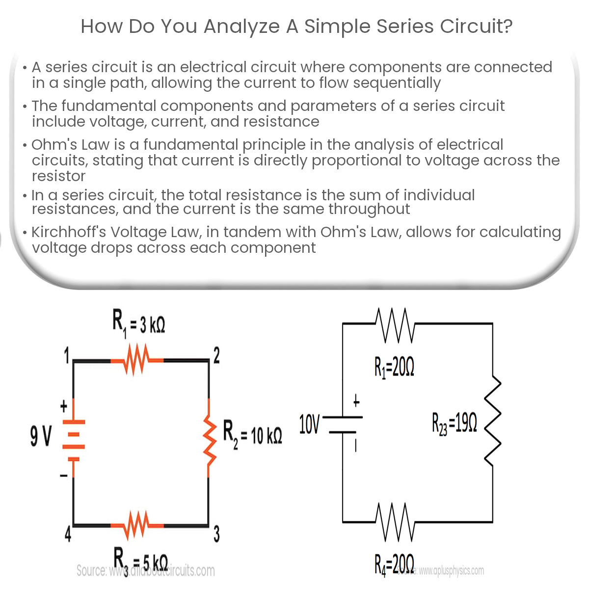
Third, the total resistance in the circuit is the sum of all the individual resistances. Each component (like a light bulb or a resistor) offers some resistance to the flow of current. In a series circuit, these resistances simply add up. If you have three resistors with values of 10 ohms, 20 ohms, and 30 ohms, the total resistance in the circuit is 60 ohms. Makes the math fairly simple, right?
Fourth, the applied voltage is divided across the resistors. This is a biggie. The total voltage supplied by the battery (or other power source) is split up among the different components in the circuit, according to their resistance. The component with the highest resistance will "take" the largest share of the voltage. This is sometimes called voltage drop.

Understanding Voltage, Current, and Resistance in Series
3. The Interplay of Electrical Properties
In a series circuit, the dance between voltage, current, and resistance is a tightly choreographed affair. You simply can't change one without affecting the others, and understanding this interplay is crucial for analyzing and designing these circuits. Let's take a closer look at how these properties behave.
Voltage: As mentioned earlier, the voltage supplied by the power source is divided across the components. The amount of voltage each component "gets" depends directly on its resistance. A higher resistance means a larger voltage drop across that component. To calculate the voltage drop across a particular resistor, you can use Ohm's Law, which states that Voltage (V) = Current (I) * Resistance (R). Since the current is the same throughout the series circuit, the resistor with the highest resistance will have the highest voltage drop. Think of it like this: the water flowing through a narrow section of pipe (high resistance) experiences a greater pressure drop than water flowing through a wider section (low resistance).
Current: One of the defining characteristics of a series circuit is that the current is constant throughout. It's the same at every point in the circuit. This is because there's only one path for the electrons to flow, so they all have to go through each component in turn. If you increase the resistance of one of the components, you'll decrease the overall current in the entire circuit (again, according to Ohm's Law: I = V/R). Similarly, if you increase the voltage supplied by the power source, you'll increase the current.
Resistance: In a series circuit, the total resistance is simply the sum of all the individual resistances. This makes it easy to calculate the overall resistance of the circuit. Once you know the total resistance and the applied voltage, you can use Ohm's Law to determine the current flowing through the circuit. Remember, increasing the resistance will decrease the current, and decreasing the resistance will increase the current (assuming the voltage stays constant).These three parameters of voltage, current, and resistance always affects each other. If you increase the resistance of a component, the current will reduce and the voltage drop accross that component will rise. If you increase the voltage supplied to the circuit, the current will rise and voltage drop across each component will rise, and so on.

Advantages and Disadvantages of Series Circuits
4. The Good, the Bad, and the Fused
Like any electrical circuit configuration, series circuits have their own unique set of advantages and disadvantages. They're not always the best choice for every application, and it's important to weigh the pros and cons before deciding whether to use one.
One of the main advantages of series circuits is their simplicity. They're easy to design and build, requiring only a few components and simple wiring. This makes them ideal for applications where simplicity is paramount, such as basic lighting circuits or simple control systems. Furthermore, because the current is the same throughout the circuit, it's easy to monitor the current flowing through the entire circuit by measuring it at just one point.
However, series circuits also have some significant drawbacks. The biggest one, as we've already discussed, is that if one component fails, the entire circuit breaks. This can be a major inconvenience, especially in applications where reliability is critical. Imagine if your car's headlights were wired in series! If one headlight burned out, you'd be driving in complete darkness. Also, because the voltage is divided across the components, the voltage available to each component may be lower than desired, especially if there are many components in the circuit. This can affect the performance of the components. The voltage drops lower as the number of components increases.
Another potential disadvantage is that adding more components to a series circuit increases the total resistance, which reduces the current flowing through the circuit. This can dim the lights in a lighting circuit or reduce the power output of a motor. So, while series circuits are simple and easy to understand, their limitations often make them unsuitable for complex or high-reliability applications.

Examples and Applications of Series Circuits
5. Where Do You See Series Circuits in the Real World?
Even though series circuits have their limitations, they're still used in a variety of applications. Understanding these applications can help you appreciate the versatility of this basic circuit configuration.
One common example is in Christmas tree lights. Although many modern Christmas light strings use parallel circuits (to avoid the "one bulb goes out, they all go out" problem), older strings often used series circuits. This was a simple and cost-effective way to wire the lights, but it also meant that a single burned-out bulb could ruin the entire display. Another example is in some types of fuses. Fuses are designed to protect electrical circuits from overcurrents. They're typically wired in series with the circuit they're protecting, so that if the current exceeds a certain level, the fuse will melt and break the circuit, preventing damage to other components. We can also find these kind of circuits in some voltage divider network.
Series circuits are also used in some basic electronic circuits, such as voltage dividers. A voltage divider uses a series of resistors to divide a voltage into smaller portions. This can be useful for creating different voltage levels for different parts of a circuit. For example, you might use a voltage divider to reduce the voltage from a 9V battery to 5V to power a microcontroller. Basic series circuits are also commonly found in educational settings as examples for teaching purposes.
Despite their limitations, series circuits remain an important part of electrical engineering, and understanding their behavior is essential for anyone working with electronics. Whether you're troubleshooting a faulty Christmas light string or designing a complex electronic circuit, a solid grasp of series circuits will serve you well. So, get hands-on, experiment with some basic circuits, and see for yourself how these fundamental principles work in practice!
